Premise
I was introduced to FPGAs during my undergrad as part of a new DAQ system created for testing our hybrid motors. They excel at moving and processing a lot of data quickly so they shine at anything ranging from that high-speed DAQ application to guidance, video processing, etc. It piqued my interest back then but now I have the free time to teach it to myself as an extra skill to aid in future projects.
To get started, I’ve been studying the Russell Merrick ‘Getting Started With FPGAs’ book, otherwise referred to as the ‘NANDLAND’ book. It covers the basics for someone with zero background in Computer Engineering, and has helped me come up to speed with the basic concepts that allow FPGAs and computers in general to work. Logic gates, Flip-Flops, Registers, RAM, FIFOs and PLLs, as well as their implementation in Hardware Description Languages. I will be learning VHDL particularly because of its syntax, as it is more human readable and strongly-typed, keeping me from developing bad habits translating from serial programming languages over to HDLs. Due to the nature of HDLs and FPGAs in general, it’s detrimental to think in individual instructions when the code is being synthesized into circuitry within the FPGA. Additionally, VHDL is widely used in critical applications in Aerospace and Defense, so it applies more to my background than Verilog.
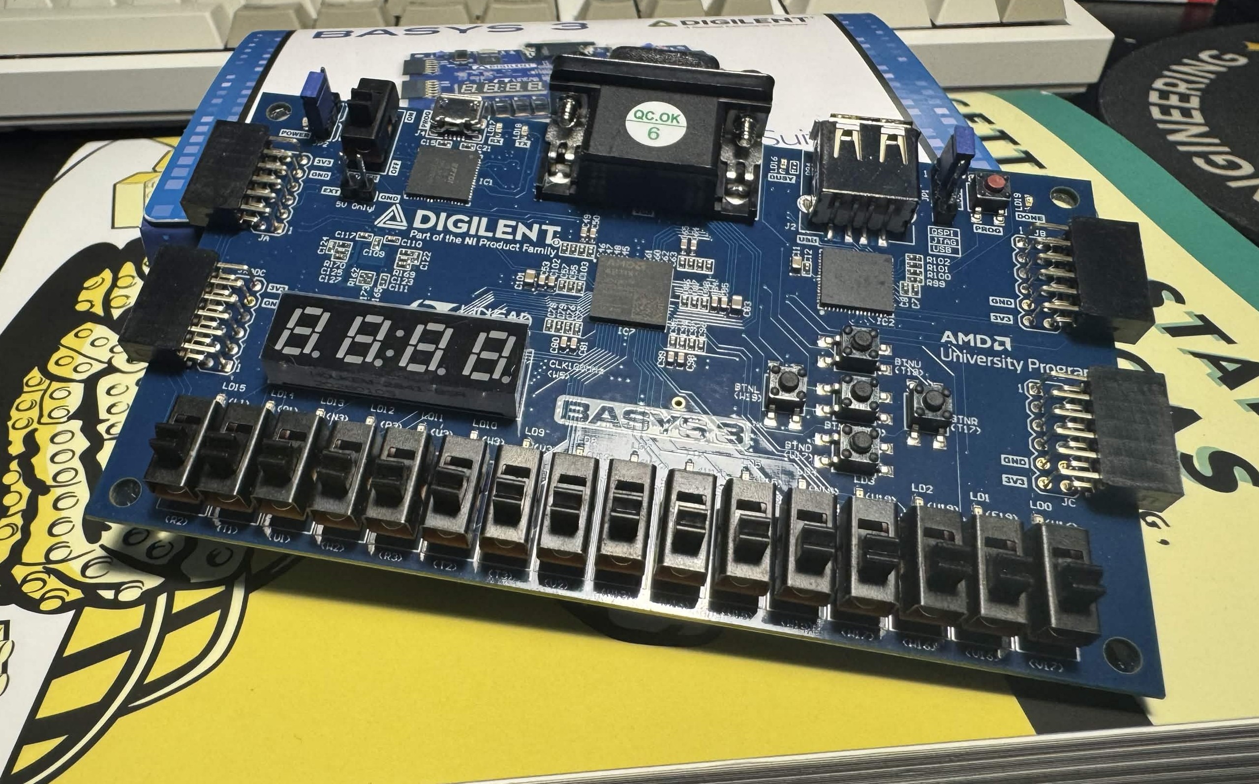
These projects will all be developed for the Digilent BASYS3 FPGA, based on the AMD/Xilinx Artix 7 family of FPGAs, the chip in specific being the XC7A35T-1CPG236C. I chose AMD because I had already had the chance to play around with the Vivado toolchain and UCF uses these FPGAs to teach Computer Engineering courses, so I already had colleagues with experience to ask. There’s also plenty of on-board peripherals along with the Digilent Pmod ports to allow me to expand once I got comfortable developing on it.
First Project: VGA Output
An overarching goal for learning is eventually move onto graphics and video processing. I’d like to be able to apply overlays to high-resolution camera feeds and show it on a screen with minimal delay, something that microcontrollers somewhat struggle at similar price points. I’m getting started by implementing a basic VGA 640 x 480 signal output from scratch and moving onto other standards/larger resolutions later on.
VGA Standard
VGA is the most basic display standard to implement digitally. It’s heavily tied to the analog realm as its roots come from feeding the deflection coils of CRT monitors of yesteryear. It’s composed of 3 color signals and 2 synchronization signals. With careful timing via a pixel clock, the monitor can reconstruct a coherent image from the combination of these signals. The pixel clock determines the resolution and our horizontal and vertical sync pulses tell the monitor when to draw a new line and when to draw a new frame, respectively. Let’s focus on the sync side of things for now.
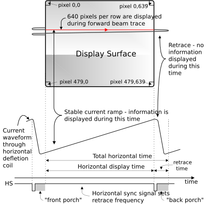
As pictured above, the horizontal sync pulse tells the monitor when a new frame begins/ends, and combined with the overall pixel clock, determines where on the screen any given pixel is being drawn. As mentioned before, the electron beam used to scan across the phosphors of the screen, so the sync pulse determined when the beam was supposed to be shot back to the left side of the screen in order to begin a new line.
With older monitors, this electron beam needed a non-zero amount of time to slow down after finishing a scan line and moving onto the next one, as well as speeding up to a steady state before drawing the new line. Because of this limitation, built into the timing signals are a “front porch” and a “back porch”. They are blank portions of the scanning process that allowed some leeway for the beam to return to the start, and although not as critical for modern screens, it was grandfathered into the standard. For a 640 by 480 signal refreshing at around 60Hz, the front porch and back porch of the horizontal sync signal are 16 and 48 ‘pixels’ each, respectively.
With this in mind, 640 active pixels and a sync pulse width of 96 ‘pixels’, our total pixel length for a horizontal line comes up to 800 pixels total. This means that for every 800 pulses of our pixel clock, a new line is started. Notice, however, that for a large portion of the line we cannot output anything and those pixels are simply in there for timing. These are all guidelines to keep track of when designing the counters to drive our sync pulses and the rest of the screen. They’re extremely useful because at any given moment we know exactly where on the screen we’re supposed to be, which can be used to control output enable signals and even drive our memory addresses in order to put data on the screen where it’s supposed to be.
To summarize:
| Horizontal Timing Region | Duration (in pixels) |
|---|---|
| Active Pixels | 640 |
| Front Porch | 16 |
| Sync Width | 96 |
| Back Porch | 48 |
| Total Blanking Interval | 160 |
| Total Horiz. Pixels | 800 |
Much like the horizontal lines, our circuit must also keep track of where on the frame we are vertically. For every vertical refresh, there are 480 horizontal sync pulses + the vertical front and back porch + the vertical sync pulse width, giving us a total of 525 lines. As an example, if the horizontal counter is at 350 and the vertical counter is at 350, it would put the ‘beam’ at 350,350 within the active portion of the screen. If we’re at 750, 350, however, it can be implied that no output should be sent to the monitor.
Similarly:
| Vertical Timing Region | Duration (in pixels) |
|---|---|
| Active Pixels | 480 |
| Front Porch | 10 |
| Sync Width | 2 |
| Back Porch | 33 |
| Total Blanking Interval | 45 |
| Total Horiz. Pixels | 525 |
In terms of the pixel clock, for this resolution the specification calls for a clock running at 25.175MHz, which our FPGA PLLs cannot provide at our master clock frequency of 100MHz. Luckily, displays are designed with a +/- tolerance of 5% which puts a 25MHz clock in the valid zone. I am not responsible for damage to older CRT monitors where the timings are infinitely more relevant in order to keep the tube happy, but for modern LCD displays it SHOULDN’T damage anything. Later on, I plan to move onto 800 by 600 which runs at a perfectly round 40MHz, and all my code here will be designed with the ability to scale up and down.
Horizontal and Vertical Sync
Both pulses are active low, meaning the signal will go low for the duration of the pulse, and return to a high state when idle.